
25.6V 208AH 5.3KWH
USER MANUAL
This manual introduces the LBSA Smart Battery by Lithium Batteries SA. Please read this manual before installation of the battery module and follow the instructions carefully during assembly. For any uncertainties, please contact Lithium Batteries SA for advice and clarification.
LBSA lithium iron phosphate (LifePO4) battery pack is a household renewable energy storage solution developed and produced by Lithium Batteries SA. After full installation, it is a low-voltage DC battery system with an operating voltage of 25.6V, and works with a low-voltage inverter to realize the goal of energy storage for home application. The battery pack supports parallel connection to expand capacity, which can meet various capacity requirements. It has a built-in battery management system (BMS), which can manage and monitor the pack and cell information including voltage, current and temperature. What's more, the BMS can balance cells when charging and discharging to extend cycle life.
It is very important and necessary to read the user manual carefully before installing or using the product. Failure to do so or to follow any of the instructions or warnings in this document can result in electrical shock, serious injury, or death, and could damage the battery or render it inoperable.
| 1.1. Precautions |
|---|
| • If the battery pack is stored for a long time, charge the battery every 3 months with SOC no less than 90%. |
| • Recharge the battery within 12 hours after a full discharge. |
| • Disconnect all battery pack terminals before performing any maintenance. |
| • Do not use cleaning solvents on the battery pack. |
| • Avoid exposing the battery pack to flammable, harsh chemicals or corrosive gasses/liquids. |
| • Do not paint any part of the battery pack or its components. |
| • Avoid extended direct sunlight exposure. |
| • Never connect the battery pack directly to PV solar wiring. |
| • Do not insert foreign objects into any part of the battery pack. |
| 1.2. Warning |
|---|
| • Do not touch the battery pack with wet hands. |
| • Never crush, drop or puncture the battery pack. |
| • Always dispose of the battery according to local safety regulations. |
| • Store and charge the battery as per instructions in this manual. |
| • Ensure reliable grounding during installation. |
| • Do not reverse polarity when connecting the battery. |
| • Avoid short circuits. Remove metallic jewelry during installation. |
| • Disconnect all loads and turn off power before installation or maintenance. |
| • Do not stack more batteries than recommended. |
| • Using a damaged battery may lead to fire hazards. |

| • Battery cell is a 3.2V 104Ah aluminium case prismatic cell. |
| • Battery cell is made from lithium iron phosphate (LiFePO4) with safety performance and longer cycle life. |
| • BMS has over-discharge, over-charge, over-current, high and low temperature warning and protection functions. |
| • BMS monitors charge and discharge state, and balances current and voltage of each cell. |
| • 125A DC Circuit Breaker with additional Shunt Tripper for auto trip function. |
| • Flexible configuration: up to 16 packs can be connected in parallel with 8 DIP switches. |
| • Operating temperature range: -20℃ to 50℃ (charging 0℃–50℃, discharging -20℃–50℃), with excellent cycle life. |
 |
Pack V: Total voltage of the battery pack Current: Negative = discharging; Positive = charging SOC: Current battery percentage Warn: 'N' = no warning; 'Y' = warning (check menu) |
 |
Cell V: View cell balance under load, difference must not exceed 100mv Temperature: 4x sensors in battery, plus environmental and PCB sensor |
 |
OV/UV Warn & Prot: Pack V must be between 44V - 56.2V. Cell mv difference ≤ 150mv. |
 |
OT: Must be < 50°C UT: Must be > 5°C |
 |
OC Warn & Prot: Charge ≤ 50A; Discharge ≤ 100A CAPA: SOC is low OFF-USE: Battery is disabled due to multiple warnings SCP: Short circuit detected |
 |
FCC: Battery capacity in Ah Rm: Remaining Ah CycleTime: Count of charge/discharge cycles |
Working light: Green LED to show the battery working status. Details as follows:

Reset: Reset button: To start the battery pack, press the button down to turn on the battery pack.
SOC light: 4 green LED lights to show the capacity status of battery pack. Each LED represents 25% of the capacity.

Alarm: ALARM light: red LED flash to show the battery alarm status. OFF Solid Green Solid Green Solid Green Solid Green Solid Green Solid Green Solid Green and red light permanently to show the battery in protection status of abnormal temperature, over-current, or short-circuit.
P+/P: Power terminals: one pair of 125A power terminals to go directly to a single inverter if one pack is used. If more than one pack is used the batteries must be connected to a busbar with equal length cable to ensure there is equal discharge and charge between the batteries. Power cable uses 10.0mm lug to connect to the battery terminals.

3.2V 104Ah lithium iron phosphate (LiFePO4) aluminium case prismatic rechargeable battery cell.
| Nominal Voltage | 3.2V |
| Nominal Capacity | 104Ah |
| Weight | ≤1.9Kg |
| Self-discharge Rate | ≤3.5% per month |
| Initial Internal Resistance (1KHz) | ≤0.35mΩ |
Refer to the cell specification for more detailed information.
The BMS is applied to monitor current, voltage, temperature, protection against over-charge, over-discharge, over-current, over-temperature, under-temperature and short circuit. The BMS provides cell balancing and current limitation during the charging process to ensure a reliable safety and performance. This capacity will be influenced by the temperature as the cells generally have less capacity available under very cold temperatures.
| BMS Functions |
|---|
| ● Over charge protection |
| ● Over discharge protection |
| ● Overcurrent protection |
| ● Cell balancing |
| ● Temperature protection |
| ● CAN communication to inverters and RS485 communication between battery packs |
SPECIFICATIONS
| Basic Parameters | |
|---|---|
| Nominal Voltage (V) | 25.6V |
| Nominal Capacity (Ah) | 208Ah |
| Nominal Power (kWh) | 5.3 kWh |
| Dimensions (mm) | 630mm*345mm*137mm |
| Weight (Kg) | 42KG |
| Discharge Cut-off Voltage (V) | 22V |
| Charge Voltage (Bulk + Absorption) (V) | 28V |
| Max Discharge Current (A) | 100A |
| Recommended Charge Current | 75A |
| Communication Interface | CAN |
| Configuration | 2P8S |
| Working Temperature |
0~50℃(Charge) -20~50℃(Discharge) -20~55℃(Storage) |
| Cell chemistry | Lithium iron phosphate (LiFePO4) |
| Cycle life | ≥80% capacity state after 4800 cycles at 0.5C, 25℃, 100% DOD |
| IP level | IP 20 |
CAN CAN communication interface: follow CAN BUS protocol, for output pack information to the inverter.
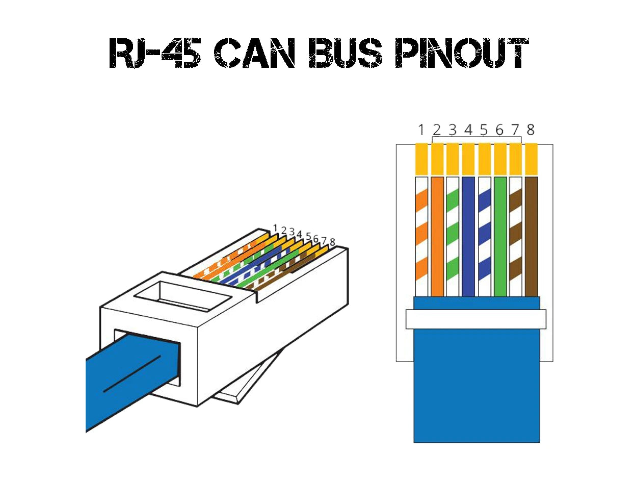
| Pin 3 | Ground |
| Pin 4 | CAN-H |
| Pin 5 | CAN-L |
RS485 Communication interface: RJ45 port, follow RS485 protocol. For transmitting battery pack information between paralleled packs, use a standard RJ45 cable. This pack is compatible with any LBSA SMART batteries.
| Pin | Definition |
|---|---|
| PIN 1, 8 | RS485-B |
| PIN 2, 7 | RS485-A |
| PIN 3, 6 | Ground |
| PIN 4, 5 | NC (Bridge weld) |
ADS Switch: To set up the battery address, and to communicate between the battery and the Inverter. Down = 'OF' Up = 'ON.


(with regards to CANbus Communication), all other inverters should have the charge and discharge cut-off set with accordance to section 2.2 in the Manual)
| Inverters | Comms Cable | Settings |
|---|---|---|
| (Pin 4 and 5 on the LBSA BMS CAN and pin 7 and 8 on the VE.CAN) | Set the port speed of the VE.CAN port to 500kbit/s. | |
| (Straight RJ45 cable to be used from the battery CAN port and the inverter CAN port) | Inverter to LI - PTCL52 | |
| (Straight RJ45 cable to be used from the battery CAN port and the inverter CAN port) | Set battery to PN-GDLT and set inverter to Default (lithium 100AH) | |
| (Straight RJ45 cable to be used from the battery CAN port and the inverter CAN port) | Set inverter to Lithium 00 | |
 |
(For Luxpower models before September 2022 refer to the Luxpower to LBSA document to be obtained from your supplier. For newer models use straight pin to pin connection. NB: BATTERY CAN PROTOCOL NEEDS TO BE SET TO LUXPOWER USING THE BATTERY MONITOR CABLE SUPPLIED BY LBSA) | Set inverter to Lithium - Battery brand 06 (LBSA BMS to be set to Luxpower) |
 |
(Straight RJ45 cable to be used from the battery CAN port and the inverter CAN port) | Set inverter to Lithium Battery LV. |
| (Straight RJ45 cable to be used from the battery CAN port and the inverter CAN port) | Set battery to PN-GDLT and set inverter to Pylontech. |
When connecting the batteries in parallel the batteries should be connected to a central busbar and from the busbar be distributed to the inverters with equal cable lengths. This unit is compatible with all LBSA SMART batteries. Terminals must not be torqued more than 6nm. M8 rawl bolts to be used to mount the wall bracket to a wall (please ensure that the surface/structure/wall is capable of carrying the unit weight.
Ensure a secure mounting surface that can support the weight of the battery. Use a 14mm/12mm drill bit (depending on a Rawl bolt of your choice) to drill two holes in the wall approximately 270mm apart. (use the bracket as a guide) Mount the bracket to the wall by using M6/M8 Rawl bolts. The mounting points of the bracket need to be flush against the wall. Once the bracket is secure you can screw your two mounting studs into the top middle Rivet nuts at the back of your battery. You must then slide your battery into the two central slots of your bracket.


| Questions | Answers |
|---|---|
| What are the DIP switch settings for one battery? | All DIP switches must be off when there is only one battery installed. |
| How many batteries can be connected in parallel? | The BMS in an LBSA battery can connect up to 16 units in parallel with full communication. However, there is no limit on the number of batteries that can be connected in parallel without communication as long as all wires are of equal length going to a central busbar. |
| What are the DIP switch settings for one battery? | All DIP switches must be off when there is only one battery installed. |
| 25.6V 208AH 5.3KWH | DESCRIPTION | VIEW PDF |
|---|---|---|
| User Manual | Instructions and usage guide for the battery |
|
| Specification Sheet | Detailed specifications about the product |
|
| General Information | Port functions, mounting of battery information, communication cables, etc |
|
| TYPE | DESCRIPTION | DOWNLOAD |
|---|---|---|
| Communication Driver | Used to connect the battery to compatible inverters. |
|
| BMS Monitor | BMS firmware version 2.8 and lower |
|
| NEW BMS Monitor | BMS firmware version 16.4 and higher |
|
This document is subject to change without notice. ©2023 Lithium Batteries SA 54 Mimetes Rd, Denver, Johannesburg, 2011 South Africa